Slides: https://docs.google.com/presentation/d/1gHT2jvUKvlXMnYtVWEIUrvUUhF3NWJ_cIzHXQDFjZsQ/edit?usp=sharing
Workshop by Preston Zen (linkedTFin.com/in/prestonzen) & Ram Gunduz (linkedin.com/in/ram-g-us) – [email protected]*
Welcome to the VOID. You didn’t come here to play Candy Crush. You came here to bend the 2.4GHz spectrum to your will, one solder joint at a time. In this guide, we’re going to walk you step-by-step through assembling your Black Hole Badge Proof-of-Concept Edition — and for the breadboard warriors, we’ve got you covered too.
Whether you’re soldering on the hotel floor at DEFCON while sipping questionable “coffee” or building in your lab, you’re about to create something that makes WiFi cry and Bluetooth beg for mercy (within a friendly 6-inch POC range, of course 😉).
🛠 Parts You’ll Need
For Black Hole Badge Edition
-
1x ESP32 (Your spectrum-bending brain)
-
2x nRF24 modules (The RF hammers)
-
1x SAO header or OLED 0.96" screen (Optional, but let’s be honest — you want it)
-
2x Capacitors (Smooth those power spikes)
-
1x JST Female connector (For power in, because wires hanging off is DEFCON chic)
-
1x Switch – either:
- A 4mm spaced sliding switch, OR
- A jumper wire from the middle hole to the hole above it (skip the anchor hole)
-
1x 3xAA battery holder with built-in sliding switch (This will be our main power switch — the board can get spicy hot, so keep that control handy)
-
3x AA Batteries (4.5V nominal; supports up to 5V officially; tested for surges up to ~15V without bursting into flames — but don’t be that guy)
For Breadboard Edition
-
Everything above, plus:
- Breadboard (your prototyping playground)
- LEDs (for status indication / pretty lights to make it look like you know what you’re doing)
-
Wiring according to provided schematics (yes, you actually have to follow them, hacker)
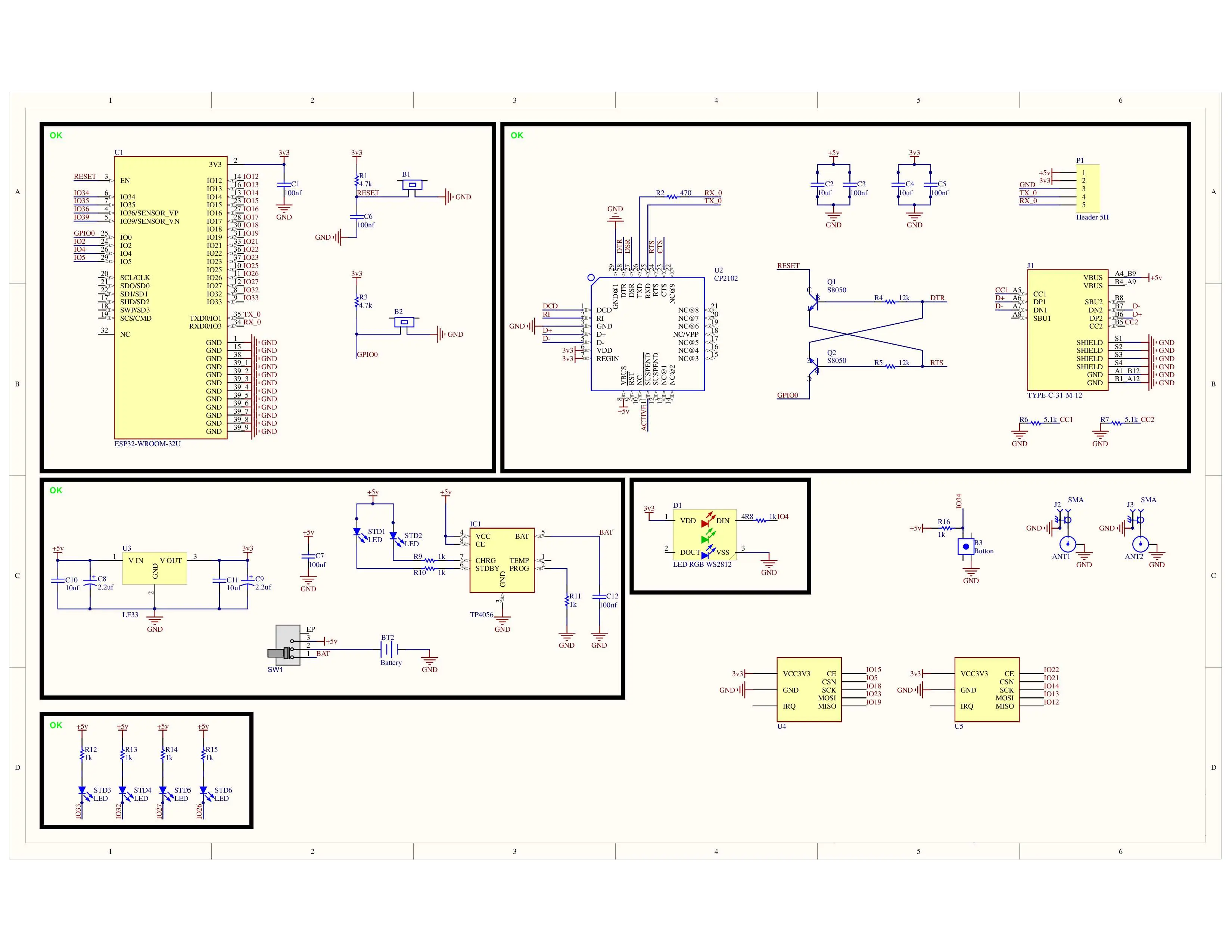
Full diagram
https://drive.google.com/file/d/1lALGdTm9qA5tEFUBaVzKo4QIp6_Bmbuy/view?usp=sharing
🔧 Step-by-Step Assembly – Black Hole Badge Edition
Step 1 – Place the ESP32
- Pop your ESP32 onto the badge PCB. This is your central command CPU, your war room, your general in the RF apocalypse.
- Make sure the orientation matches the silkscreen on the board (USB port facing the correct edge — unless you want to play “debug the upside-down solder job” later).
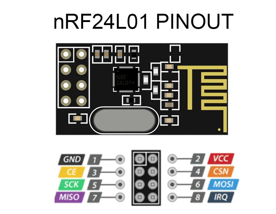
Step 2 – Add the Twin nRF24 Modules
- These are your spectrum enforcers.
- Insert two nRF24s into their respective headers or solder points.
- Double-check pin alignment — VCC to VCC, GND to GND, MOSI/MISO/CSN/CE exactly where they belong. One wrong connection and you’ll be jamming yourself instead.
Step 3 – Optional SAO / OLED 0.96"
-
If you’re adding an OLED screen for real-time status flexing:
- Solder it to the SAO header or directly wire to the ESP32’s SDA/SCL pins.
- Mount it so you can actually see it during operation (unless you’re into surprise data).
Step 4 – Drop in the Capacitors
- These are the shock absorbers for your power system.
- Place the two capacitors in their marked positions, polarity respected (unless you enjoy capacitor confetti).
- This will help smooth voltage ripples from your battery pack or when someone decides to “test” your badge by touching the power rails.
Step 5 – Install the JST Female Connector
- This is your external power interface.
- Solder it clean, keep the pins straight, and make sure the connector faces outward for easy plugging/unplugging.
Step 6 – Switch It Up
You have two options for your on/off control:
- 4mm Spaced Sliding Switch – Install it in the dedicated slot and solder the pins.
- Jumper Method – If you’re skipping the onboard switch, run a wire from the middle hole to the hole above it (skip the anchor hole). This essentially bypasses the switch.
⚠ Pro Tip: Since the battery holder already has a switch, most folks just skip the onboard one. Less solder, more time for lockpicking village.
Step 7 – Power Connection
- Attach your 3xAA battery holder via the JST connector.
- This will output 4.5V nominal, well within the ESP32’s happy zone (officially supports up to 5V).
- Unofficially, we’ve tested surges up to 15V. It survived, but that’s like saying you survived a DEFCON pool party — doesn’t mean you should repeat it.
💡 Breadboard Edition Build
- Same component list as the badge build.
- Use the provided schematic to wire the ESP32, dual nRF24s, OLED, capacitors, JST power input, and LEDs.
- LEDs can be hooked to ESP32 GPIO pins to indicate attack active, idle, or just to blink in a menacing hacker way.
- This version is great for learning and tinkering without committing to permanent solder joints.
⚡ Power-On & Testing
- Insert batteries and flick the switch on the battery holder.
- If you installed an OLED, you should see it light up.
- Install the Windows ESP-32 drivers (RIP if you have mac or linux unfortunately)
- Load one of the supported firmwares (recommended: ESP32-BlueJammer) via USB.
- Place your test device (phone, drone controller, etc.) within 6 inches.
- Observe the glorious short-range chaos.
⚠ DEFCON Legal Disclaimer
This is a proof-of-concept RF research platform with a 6-inch range limit for compliance and safety. Don’t point it at strangers’ devices unless they’ve consented — we don’t want to be explaining your arrest over pancakes at Hash House A Go Go.